Novel Design of Optical Sensor
Based on Two-Dimensional Photonic Crystals for the Detection of Volatile
Organic Compounds that can Infect Human Health
Type of article: Original
Abstract
Background: In recent research, optical sensors gained
a growing interest motivated by the increasing need for specific sensors that
allow for routine and effective measurements in several fields and analysis
such as, safety, environment, and human health. Among optical sensors are
photonic crystal sensors, which are characterized by high sensitivity and
biocompatibility. The variations inside and around the photonic crystal can give
important information by measuring the wavelength, the band gap, the output
power…etc. Through defects created in photonic crystals such as missing rows of
holes or rods, light is guided through and the goal is to achieve a very high
sensitivity and spatial selectivity to changing superior bulk devices. In this study,
we model a new structure of an optical channel drop filter (CDF) based on 2-dimensional
photonic crystals to detect volatile organic
compounds that can infect human health.
Objective: Detect the
variation of the refractive index by fixing the radius (r) at 99.37nm and the
lattice constant (a) at 523nm for various volatile organic compounds such as H2CO,
CH2Cl2, and C2Cl4 with refractive
indexes that are: 1.3746, 1.421 and 1.503 respectively in the optical sensor
based on photonic crystals for reasons related to the protection of human
health.
Methods: The structure is
made of square lattice silicon rods immersed in air. The dielectric constant of
silicon and air is 11.9716 and 1 respectively. First, we created a cross shape
resonator and designed an optical channel drop filter in the heart of the
structure; our method is based on plane wave expansion method
(PWE) by using MATLAB software and the finite element method (F.E.M) with
COMSOL software.
Results: Three volatile compounds have been studied,
such as Dichloromethane used as synthesis intermediate by the chemical industry
or solvent used in the pharmaceutical or medical industry. Acute inhalation
exposure may cause severe optic neuropathy and liver attack (Hepatitis). Then,
the Methanal is used to dry or kill the skin taking
as an example, the medical treatment of warts. And perchlorethylene
is used for the dry cleaning of tissues and for degreasing metals because it is
in category 3 carcinogens, toxic to the nervous system and the kidney. These
three volatile compounds where introduced and studied in the proposed
structure. The results obtained through this study are as follows:
1- diagram of the TM and TE bands of
the photonic crystal in a square array of silicon rods embedded in the air,
2- schematic diagram of the filter,
3- distribution of the refractive index
along the structure,
4- structure meshing,
5- propagation and transmission for
different refractive indices such as methanal (H2CO),
dichloromethane (CH2Cl2) and perchlorethylene
(C2Cl4).
Conclusion: In this article, we have been able to
simulate, analyze and control our proposed structure with MATLAB and COMSOL
software based on the finite element method. The results show that for the
three volatile organic compounds, the variation of the signal is due to the
wavelength of the resonance which is related to the refractive index (n). This can
be seen by the small Δλ between three volatile
organic compounds, which is 0.4nm between (H2CO, C2Cl4)
and 2.9 nm between (CH2Cl2, H2CO). Thanks to
this change, this structure can be used as sensor for the detection of toxic
organic pollutants that can infect human health (16).
Keywords: Photonic crystal, finite element method, volatile organic compounds, ring resonator, human health
Corresponding author: Mr Ghoumazi Mehdi, Université Mohamed boudiaf de M’Sila, Algeria. Email:g_mehd@yahoo.fr,
Received: 06 July,
2018, Accepted: 02 December, 2018, English editing: 04 January, 2019,Published: 05 January, 2019.
Screened by iThenticate..©2017-2019 KNOWLEDGE KINGDOM PUBLISHING.
1. Introduction
In recent years, a lot of research using
photonic crystals as a detection element for sensing was undertaken due their
confinement of light and band structure (1).
Photonic crystals used as a sensor have
seen massive development in case of a rising demand of sensing applications in
several fields such as: security, healthcare and environment (2). These
photonic crystals are periodic dielectric structures and good candidates to build
different components for compact application systems. The electromagnetic waves
with the photonic Bandgap are prohibited to propagate (3) leading to a lot of
interesting phenomena, like photonic crystal laser, optical coupler (4),
Optical filter (5), optical switching, high
quality (Q) cavity (6) and so on. To calculate the dispersion curves of
photonic crystal, there are several theoretical and numerical development tools
such as: finite-difference time-domain (FDTD) method (7), multiple
multipole methods (8), plane wave method (PWM) (9) and Finite element method
(FEM). Among these methods, we used finite element method based on COMSOL
software.
First, we designed 2D Square lattice of photonic crystals structure and perform
theoretical computing using the plane-wave expansion (PWE) method for the
modeling of the EM wave propagation inside the PC. Besides, we have also shown
the first Brillouin zone, which contains the TM and TE mode (Fig.1 (red
section)) (10).
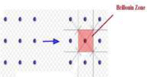
Fig.1. the reciprocal lattices (dots) and corresponding first
Brillouin zones of square lattice (10)
In this work, we examine the
photonic band structure, propagation use (PWE) and transmission of 2D photonic use
by the finite element method (FEM) (11-14) with a commercial software COMSOL Multiphysics® (15).
2. Materials and Methods
Our proposed structure is designed by 31X25
square lattice of dielectric rods embedded in air. The refractive index and the
radius of dielectric rods are 3.46 and r=0.19*a respectively. Where ‘a’ is the
lattice constant of the PC structure and its value is 523nm. We applied the
finite element method to calculate the dispersion relation of the square
lattice pattern for (TM / TE) polarizations. The light propagation is
considered in the xy-plane. Fig.2 is showing three
photonic band gaps. Next, the simulations will be adjusted to the proposed
structure of a channel drop filter (CDF) based on two dimensional photonic
crystal ring resonator (PCRR).
As shown in Fig. 2, the two first photonic
band gaps (PBGs)
in TM mode are with brown color and one in TE mode with purple color. The TM PBGs
are in 1215.99 nm< λ< 1809.68nm and 693.26nm< λ< 725.28nm range and
the TE PBGs is in 628.07nm < λ< 634.47nm range.
We took the first Photonic band gap (PBG) in TM mode
where λ is [1215.99, 1809.68] nm this is due to the large width covered by sufficient
wavelengths for optical communication applications.
The next step consists in realizing our filter in a fundamental platform as mentioned below: By removing a complete row of dielectric rods in the Γ-M direction to create the bus waveguide and removing some rods in the M-X direction we created the output waveguide. After that, we created across shape resonator between bus and the output waveguide.
The final design of the structure filter is depicted in Fig.3.
The structure consists
of two waveguides in horizontal direction (Γ-M) and perpendicular direction (M-X) and a single cross shape of photonic crystal ring
resonator (PCRR). The top waveguide is named as bus waveguide and its input
port in the left side is marked Port 1 while the other side of the top
waveguide is marked Port2. The bottom waveguide is known as dropping waveguide
and its output port in below side is marked Port 3.
We observed that the structure driven mechanism could be summarized as follows: from the entrance of the structure, the optical waves pass straight to the port 2. In the meantime, at a desired wavelength, wavelengths go down to the waveguide through a cross shape resonant ring and move to the port 3. Furthermore, we investigate and replace the refractive index of the frame surrounding the resonator by three refractive indices, which belonged to the family of toxic organic pollutants such as: H2CO, CH2Cl2 and C2Cl4. The refractive index rods, which changed, is labelled with a blue circle as shown in fig.4.
To define this structure, we used a scalar
equation for the transverse electric field component Ez,
- [Δ.Ez
+ (n*k0)2] = Ez
(1)
Where n is the refractive index and k0 is the free-space wave number (15).
3. Results
As mentioned
above, Fig.2 depicts three photonic forbidden bands (PBGs), two PBGs for the TM
mode (brown grid) and one for the TE mode (purple grid) of the photonic crystal
in the square array of silicon rods in the air, radius = 0.19a.
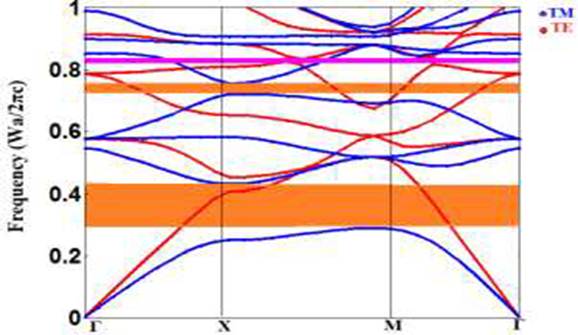
Fig.2. The
calculated diagram bands with FEM of TM and TE of the Photonic crystal in the square
lattice of Silicon rods in Air, radius=0.19a.
Also, Fig.3 shows the final structure of
the filter.
 .
.
Fig.3. The
schematic diagram of the filter
Fig.4 years Fig.5
represent the distribution of the refractive index and the mesh along the
proposed structure

Fig. 4. The
distribution of the refractie index in the proposed
structure
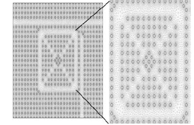
Fig.5. The
proposed structure with mesh

Fig.6. The propagation of the field
distribution of the proposed CDF for different refractive index of H2CO, CH2Cl2
and C2Cl4 respectively at λ = 1550nm
.
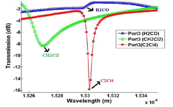
Fig.7.The transmission for different refractive index
of H2CO, CH2Cl2and C2Cl4respectively.
4. Discussion
By using the COMSOL
software, we obtained the modeling results from the RF module whose goal is to
solve the Maxwell’s equations for the distribution of the optical field and to
extract the optical properties of the photonic crystals. In this article, we
focus our investigation on the influence of the chosen volatile organic
compounds materials, such as: H2CO, CH2Cl2 and
C2Cl4 by changing the refractive index (n) of the frame
and the cross shape resonator at the same time (see figure.3 (red color)). From the simulation, we released the
distribution of the electric field component (E) and the transmission of three
volatile organic compounds (H2CO, CH2Cl2 and C2Cl4)
in the structure (see Fig. 6). Realizing that the spread is on the (xy) plane, the transmission range of the magnetic field is
appeared in Fig.7 for a wavelength, which changes from 1.52 μm up to 1.54μm which is an interim related with the PBGs figured by
the plane wave technique (PWE) as it was mentioned in the principal area.
In Figure 7, the
transmission in dB of the structure is represented by port 3 for the three
volatile organic compounds (H2CO, CH2Cl2 and C2Cl4) whose curves are
respectively blue, green and red. It can be seen that for the different
materials used, the transmission coefficient reaches maximums at the resonance
wavelength. In the case of H2CO, we observe that the transmission coefficient
reaches the value of -1.7486 dB for a wavelength λ = 1529.9nm. Then, for CH2Cl2
it is -8.3274 dB for a wavelength of 1527nm and for the last material C2Cl4 the
transmission coefficient completes a value of -15.8246de the wavelength λ =
1530.3nm.
Note that the three
transmission coefficients that we were able to obtain are classified as
follows: Dichloromethane, methanal, and perchlorethylene, respectively. The difference in resonance
wavelength between CH2Cl2, H2CO equal to 2.9nm and between H2CO and C2Cl4 equal
to 0.4 nm this is due to the refractive index which varies from one volatile
organic compound to another (16).
5. Conclusions
In this summary, a modeling of a photonic crystal filter structure with a cross resonator ring using the finite element method was simulated, analyzed and controlled by the COMSOL software. The results obtained by COMSOL show different attitudes of signal for three volatile organic compound materials (H2CO, CH2Cl2 and C2Cl4). This change in signal is due to the resonance wavelength of the filter which depends on the refractive index (n) and which is manifested by a wavelength difference (Δλ) of 0.4 between (H2CO, C2Cl4) and 2.9 nm between (CH2Cl2, H2CO). This structure can be used as a sensor for the detection of toxic organic pollutants that can infect human health.
6. Acknowledgments
The Ministry of Higher Education and
Scientific Research of Algeria supported the present work
7. Conflict of Interest
There
is no conflict of interest to be declared. All authors contributed to this
project and article equally. All authors read and approved the final
manuscript.
8. Author’s
biography
Mehdi Ghoumazi is a Ph.D. student in electronics at
Department of Electronics, University of Mohamed Boudiaf
of M’sila, Algeria. After received his degree in
electronic engineering in instrumentation in 2006 and magister degree (2009) in
microelectronics optic and hyper frequency at the University of Constantine
Algeria, he started working as researcher at Advanced Technologies Development
Center (CDTA) in Setif, since 2014. His researches
interests are doped optical fibers, crystal photonic based on optical devices
used for sensing.
Abdesselam Hocini received his Ph.D., magister and engineer degrees in
electronics instrumentation in 2000, 2002 and 2008, all from Constantine
University, Algeria. He is currently an assistant professor in Department of
Electronics at University of Mohamed Boudiaf of M’sila, Algeria. His research interests include the design
and characterization of photonic devices. In particular, his research concerns
sensing, solar cells and realizing advanced functional photonic crystal
devices.
Messaoud Hameurlain and Mokhtar Boudaa began working as
a research support engineer at the Advanced Technology Development Center
(CDTA) in Sétif since 2014.
9.References:
1)
Benmerkhi A, Bouchemat M, Bouchemat T: Influence of eleptical shaped holes on
the sensitivity and Q factor in 2D photonic crystals sensor. Photonics and
nanostructures- Fundamentals and Applications. 2016 Jul; Volume 20: 7-17.
2) Benmerkhi A, Bouchemat M, Bouchemat T.
Improved sensitivity of the photonic crystal slab biosensors by using
elliptical air holes. Optik- International Journal for Light and Electron
Optics.2016July;Volume 127(14) : 5682-5687.
3) Olaye S, Dehghani AA: Nano-Pressure using
High Quality Photonic Crystal Cavity Resonator. 8th IEEE international
Symposium on Communication Systems. Networks and Digital Processing. 2012;
978-1-4577-1473-3.
4) Sevin G, Fowler D, Xu G, Julien FH,
Colombelli R, Beere H, Ritchie D: Continuous-wave operation of 2.7 thz photonic
crystal quantum cascade lasers. Electronics letters; 2010 Oct28; (46) 22.
https://doi.org/10.1049/el.2010.2036
5) Petcu
A, Preda l: The Optical Transmission Of One-Dimensional. Romanian Journnal of
Physics; 2009 Jun; Volume 54 (5) :539–546.
6) Gong Y, Vučković J: Photonic crystal
cavities in silicon dioxide. Applied physics letters 96, 2010 Jan 21; 031107.
https://doi.org/10.1063/1.3297877
7)
Movahhedi M, Abdipour A, Ceric H, Sheikholeslami A, Selberherr S: Optimization
of the Perfectly Matched Layer for the Finite-Element Time-Domain Method. IEEE
microwave and wireless components letters. 2007 Jan 8; 17(1):10-12.
https://doi.org/10.1109/LMWC.2006.887240
8)
Moreno E, Erni D, Hafner C: Band structure computations of metallic photonic
crystals with the multiple multipole method. physical revwie B, 2002 Apr 65 (15):155120
-1.
9) Sozuer H S Haus J W: Photonic Bands:
convergence problems with the Plane wave methode. Physical Review B.1992 Jun
15; 45(24).https://doi.org/10.1103/PhysRevB.45.13962
10)https://en.wikipedia.org/wiki/Brillouin_zone
11)Jin Y, Zhen-Y, Wu Z, Daouadji A: Numerical
modeling of pile penetration in silica sands considering the effect of grain
breakage. Finite Elements in Analysis and Design. 2018 May 144:15–29.
https://doi.org/10.1016/j.finel.2018.02.003
https://doi.org/10.1016/j.finel.2018.02.003
12)Grbovic A, Mihajlovic D: Practical Apects
of finite element method applications in dentistry. Balkan Journal of dental
Medecine. 2017Jul 8 .Vol 21(2): 69-77.
13)Whiteley,Jonathan. Finite Element Methods.
1red rev. Mathematical Engineering, Springer International Publishing AG; 2017.
XI, 232 p.
14)Dyson AP, Tang Z, Tolooiyan A: Use of
stochastic XFEM in the investigation of heterogeneity effects on the tensile
strength of intermediate geotechnical materials. Finite Elements in Analysis
and Design.2018 Jun; 145: 1–9. https://doi.org/10.1016/j.finel.2018.03.003
https://doi.org/10.1016/j.finel.2018.03.003
15)https://www.comsol.com/
16)Tsai WT: Toxic Volatile Organic Compounds
(VOCs) in the Atmospheric Environment: Regulatory Aspects and Monitoring in
Japan and Korea. Environments. 2016 Sept 7, 3(4) 23.
https://doi.org/10.3390/environments3030023